2. Under what conditions does electric current occur?
Electric current occurs if there are free charges, as well as as a result of the action of an external electric field. To obtain an electric field, it is enough to create a potential difference between some two points of the conductor.3. Why is the movement of charged particles in a conductor in the absence of an external electric field chaotic?
If there is no external electric field, then there is no additional velocity component directed along the electric field strength, which means that all directions of particle motion are equal.4. How does the movement of charged particles in a conductor differ in the absence and presence of an external electric field?
In the absence of an electric field, the movement of charged particles is chaotic, and in its presence, the movement of particles is the result of chaotic and translational movements.5. How is the direction of electric current selected? In what direction do electrons move in a metal conductor carrying electric current?
The direction of the electric current is taken to be the direction of movement of positively charged particles. In a metal conductor, electrons move in the direction opposite to the direction of the current.Electric current
First of all, it’s worth finding out what it is electric current. Electric current is the ordered movement of charged particles in a conductor. In order for it to arise, an electric field must first be created, under the influence of which the above-mentioned charged particles will begin to move.
The first knowledge of electricity, many centuries ago, related to electrical “charges” produced through friction. Already in ancient times, people knew that amber, rubbed with wool, acquired the ability to attract light objects. But only at the end of the 16th century, the English physician Gilbert studied this phenomenon in detail and found out that many other substances had exactly the same properties. Bodies that, like amber, after rubbing, can attract light objects, he called electrified. This word is derived from the Greek electron - “amber”. Currently, we say that bodies in this state have electrical charges, and the bodies themselves are called “charged.”
Electric charges always arise when different substances come into close contact. If the bodies are solid, then their close contact is prevented by microscopic protrusions and irregularities that are present on their surface. By squeezing such bodies and rubbing them against each other, we bring together their surfaces, which without pressure would only touch at a few points. In some bodies, electric charges can move freely between various parts, in others this is impossible. In the first case, the bodies are called “conductors”, and in the second - “dielectrics, or insulators”. Conductors are all metals, aqueous solutions of salts and acids, etc. Examples of insulators are amber, quartz, ebonite and all gases found under normal conditions.
Nevertheless, it should be noted that the division of bodies into conductors and dielectrics is very arbitrary. All substances conduct electricity to a greater or lesser extent. Electric charges are positive and negative. This kind of current will not last long, because the electrified body will run out of charge. For the continued existence of an electric current in a conductor, it is necessary to maintain an electric field. For these purposes, electric current sources are used. The simplest case of the occurrence of electric current is when one end of the wire is connected to an electrified body, and the other to the ground.
Electrical circuits supplying current to light bulbs and electric motors did not appear until the invention of batteries, which dates back to around 1800. After this, the development of the doctrine of electricity went so quickly that in less than a century it became not just a part of physics, but formed the basis of a new electrical civilization.
Basic quantities of electric current
Amount of electricity and current. The effects of electric current can be strong or weak. The strength of the electric current depends on the amount of charge that flows through the circuit in a certain unit of time. The more electrons moved from one pole of the source to the other, the greater the total charge transferred by the electrons. This net charge is called the amount of electricity passing through a conductor.
In particular, the chemical effect of electric current depends on the amount of electricity, i.e., the greater the charge passed through the electrolyte solution, the more substance will be deposited on the cathode and anode. In this regard, the amount of electricity can be calculated by weighing the mass of the substance deposited on the electrode and knowing the mass and charge of one ion of this substance.
Current strength is a quantity that is equal to the ratio of the electric charge passing through the cross section of the conductor to the time it flows. The unit of charge is the coulomb (C), time is measured in seconds (s). In this case, the unit of current is expressed in C/s. This unit is called ampere (A). In order to measure the current in a circuit, an electrical measuring device called an ammeter is used. For inclusion in the circuit, the ammeter is equipped with two terminals. It is connected in series to the circuit.
Electrical voltage. We already know that electric current is the ordered movement of charged particles - electrons. This movement is created using an electric field, which does a certain amount of work. This phenomenon is called the work of electric current. In order to move more charge through an electrical circuit in 1 s, the electric field must do more work. Based on this, it turns out that the work of electric current should depend on the strength of the current. But there is one more value on which the work of the current depends. This quantity is called voltage.
Voltage is the ratio of the work done by the current in a certain section of an electrical circuit to the charge flowing through the same section of the circuit. Current work is measured in joules (J), charge - in coulombs (C). In this regard, the unit of measurement for voltage will become 1 J/C. This unit was called the volt (V).
In order for voltage to arise in an electrical circuit, a current source is needed. When the circuit is open, voltage is present only at the terminals of the current source. If this current source is included in the circuit, voltage will also arise in individual sections of the circuit. In this regard, a current will appear in the circuit. That is, we can briefly say the following: if there is no voltage in the circuit, there is no current. In order to measure voltage, an electrical measuring instrument called a voltmeter is used. to his appearance it resembles the previously mentioned ammeter, with the only difference being that the letter V is written on the voltmeter scale (instead of A on the ammeter). The voltmeter has two terminals, with the help of which it is connected in parallel to the electrical circuit.
Electrical resistance. After connecting various conductors and an ammeter to the electrical circuit, you can notice that when using different conductors, the ammeter gives different readings, i.e. in this case, the current strength available in the electrical circuit is different. This phenomenon can be explained by the fact that different conductors have different electrical resistance, which is a physical quantity. It was named Ohm in honor of the German physicist. As a rule, larger units are used in physics: kilo-ohm, mega-ohm, etc. The resistance of a conductor is usually denoted by the letter R, the length of the conductor by L, and the cross-sectional area by S. In this case, the resistance can be written as a formula:
where the coefficient p is called resistivity. This coefficient expresses the resistance of a conductor 1 m long with a cross-sectional area equal to 1 m2. Specific resistance is expressed in Ohms x m. Since wires, as a rule, have a rather small cross-section, their areas are usually expressed in square millimeters. In this case, the unit of resistivity will be Ohm x mm2/m. In the table below. Figure 1 shows the resistivities of some materials.
|
Table 1. Electrical resistivity of some materials |
|||
|
Material |
p, Ohm x m2/m |
Material |
p, Ohm x m2/m |
|
Platinum-iridium alloy | |||
|
Metal or alloy |
|||
|
Manganin (alloy) | |||
|
Aluminum |
Constantan (alloy) | ||
|
Tungsten | |||
|
Nichrome (alloy) | |||
|
Nickelin (alloy) |
Fechral (alloy) | ||
|
Chromel (alloy) | |||
According to the table. 1 it becomes clear that copper has the lowest electrical resistivity, and metal alloy has the highest. In addition, dielectrics (insulators) have high resistivity.
Electrical capacity. We already know that two conductors isolated from each other can accumulate electrical charges. This phenomenon is characterized by a physical quantity called electrical capacitance. The electrical capacitance of two conductors is nothing more than the ratio of the charge of one of them to the potential difference between this conductor and the neighboring one. The lower the voltage when the conductors receive a charge, the greater their capacity. The unit of electrical capacitance is the farad (F). In practice, fractions of this unit are used: microfarad (μF) and picofarad (pF).
Yandex.DirectAll advertisementsApartments for daily rent Kazan! Apartments from 1000 rub. daily. Mini-hotels. Reporting documents16.forguest.ru Apartments for daily rent in Kazan Cozy apartments in all districts of Kazan. Quick daily apartment rental.fatyr.ru New Yandex.Browser! Convenient bookmarks and reliable protection. A browser for pleasant browsing on the Internet!browser.yandex.ru 0+
If you take two conductors isolated from each other and place them at a short distance from one another, you will get a capacitor. The capacitance of a capacitor depends on the thickness of its plates and the thickness of the dielectric and its permeability. By reducing the thickness of the dielectric between the plates of the capacitor, the capacitance of the latter can be significantly increased. On all capacitors, in addition to their capacity, the voltage for which these devices are designed must be indicated.
Work and power of electric current. From the above it is clear that electric current does some work. When connecting electric motors, the electric current makes all kinds of equipment work, moves trains along the rails, illuminates the streets, heats the home, and also produces a chemical effect, i.e., allows electrolysis, etc. We can say that the work done by the current on a certain section of the circuit is equal to the product current, voltage and time during which the work was performed. Work is measured in joules, voltage in volts, current in amperes, time in seconds. In this regard, 1 J = 1B x 1A x 1s. From this it turns out that in order to measure the work of electric current, three instruments should be used at once: an ammeter, a voltmeter and a clock. But this is cumbersome and ineffective. Therefore, the work of electric current is usually measured with electric meters. This device contains all of the above devices.
The power of the electric current is equal to the ratio of the work of the current to the time during which it was performed. Power is designated by the letter “P” and is expressed in watts (W). In practice, kilowatts, megawatts, hectowatts, etc. are used. In order to measure the power of the circuit, you need to take a wattmeter. Electrical engineers express the work of current in kilowatt-hours (kWh).
Basic laws of electric current
Ohm's law. Voltage and current are considered the most useful characteristics of electrical circuits. One of the main features of the use of electricity is the rapid transportation of energy from one place to another and its transfer to the consumer in the required form. The product of the potential difference and the current gives power, i.e., the amount of energy given off in the circuit per unit time. As mentioned above, to measure the power in an electrical circuit, 3 devices would be needed. Is it possible to get by with just one and calculate the power from its readings and some characteristic of the circuit, such as its resistance? Many people liked this idea and found it fruitful.
So what is the resistance of a wire or circuit as a whole? Does a wire, like water pipes or vacuum system pipes, have a permanent property that could be called resistance? For example, in pipes, the ratio of the pressure difference producing flow divided by the flow rate is usually a constant characteristic of the pipe. Similarly, heat flow in a wire is governed by a simple relationship involving the temperature difference, the cross-sectional area of the wire, and its length. The discovery of such a relationship for electrical circuits was the result of a successful search.
In the 1820s, the German schoolteacher Georg Ohm was the first to begin searching for the above relationship. First of all, he strived for fame and fame, which would allow him to teach at the university. That is why he chose an area of research that promised special advantages.
Om was the son of a mechanic, so he knew how to draw metal wire of different thicknesses, which he needed for experiments. Since it was impossible to buy suitable wire in those days, Om made it himself. During his experiments, he tried different lengths, different thicknesses, different metals and even different temperatures. He varied all these factors one by one. In Ohm's time, batteries were still weak and produced inconsistent current. In this regard, the researcher used a thermocouple as a generator, the hot junction of which was placed in a flame. In addition, he used a crude magnetic ammeter, and measured potential differences (Ohm called them “voltages”) by changing the temperature or the number of thermal junctions.
The study of electrical circuits has just begun to develop. After batteries were invented around 1800, it began to develop much faster. Various devices were designed and manufactured (quite often by hand), new laws were discovered, concepts and terms appeared, etc. All this led to a deeper understanding of electrical phenomena and factors.
Updating knowledge about electricity, on the one hand, became the reason for the emergence of a new field of physics, on the other hand, it was the basis for the rapid development of electrical engineering, i.e. batteries, generators, power supply systems for lighting and electric drive, electric furnaces, electric motors, etc. were invented , other.
Ohm's discoveries were of great importance both for the development of the study of electricity and for the development of applied electrical engineering. They made it possible to easily predict the properties of electrical circuits for direct current, and subsequently for alternating current. In 1826, Ohm published a book in which he outlined theoretical conclusions and experimental results. But his hopes were not justified; the book was greeted with ridicule. This happened because the method of crude experimentation seemed unattractive in an era when many were interested in philosophy.
He had no choice but to leave his teaching position. He did not achieve an appointment to the university for the same reason. For 6 years, the scientist lived in poverty, without confidence in the future, experiencing a feeling of bitter disappointment.
But gradually his works gained fame, first outside Germany. Om was respected abroad and benefited from his research. In this regard, his compatriots were forced to recognize him in his homeland. In 1849 he received a professorship at the University of Munich.
Ohm discovered a simple law establishing the relationship between current and voltage for a piece of wire (for part of a circuit, for the entire circuit). In addition, he compiled rules that allow you to determine what will change if you take a wire of a different size. Ohm's law is formulated as follows: the current strength in a section of a circuit is directly proportional to the voltage in this section and inversely proportional to the resistance of the section.
Joule-Lenz law. Electric current in any part of the circuit does some work. For example, let's take any section of the circuit between the ends of which there is a voltage (U). By definition of electric voltage, the work done when moving a unit of charge between two points is equal to U. If the current strength in a given section of the circuit is equal to i, then in time t the charge it will pass, and therefore the work of the electric current in this section will be:
This expression is valid for direct current in any case, for any section of the circuit, which may contain conductors, electric motors, etc. The current power, i.e. work per unit time, is equal to:
This formula is used in the SI system to determine the unit of voltage.
Let us assume that the section of the circuit is a stationary conductor. In this case, all the work will turn into heat, which will be released in this conductor. If the conductor is homogeneous and obeys Ohm’s law (this includes all metals and electrolytes), then:
where r is the conductor resistance. In this case:
This law was first experimentally deduced by E. Lenz and, independently of him, by Joule.
It should be noted that heating conductors has numerous applications in technology. The most common and important among them are incandescent lighting lamps.
Law of Electromagnetic Induction. In the first half of the 19th century, the English physicist M. Faraday discovered the phenomenon of magnetic induction. This fact, having become the property of many researchers, gave a powerful impetus to the development of electrical and radio engineering.
In the course of experiments, Faraday found out that when the number of magnetic induction lines penetrating a surface bounded by a closed contour changes, an electric current arises in it. This is the basis of perhaps the most important law of physics - the law of electromagnetic induction. The current that occurs in the circuit is called induction. Due to the fact that an electric current arises in a circuit only when free charges are exposed to external forces, then with a changing magnetic flux passing along the surface of a closed circuit, these same external forces appear in it. The action of external forces in physics is called electromotive force or induced emf.
Electromagnetic induction also appears in open conductors. When a conductor crosses magnetic lines of force, voltage appears at its ends. The reason for the appearance of such voltage is the induced emf. If the magnetic flux passing through a closed loop does not change, no induced current appears.
Using the concept of “induction emf,” we can talk about the law of electromagnetic induction, i.e., the induction emf in a closed loop is equal in magnitude to the rate of change of the magnetic flux through the surface bounded by the loop.
Lenz's rule. As we already know, an induced current arises in a conductor. Depending on the conditions of its appearance, it has a different direction. On this occasion, the Russian physicist Lenz formulated the following rule: the induced current arising in a closed circuit always has such a direction that the magnetic field it creates does not allow the magnetic flux to change. All this causes the appearance of an induction current.
Induction current, like any other, has energy. This means that in the event of an induction current, electrical energy appears. According to the law of conservation and transformation of energy, the above-mentioned energy can only arise due to the amount of energy of some other type of energy. Thus, Lenz's rule fully corresponds to the law of conservation and transformation of energy.
In addition to induction, so-called self-induction can appear in the coil. Its essence is as follows. If a current arises in the coil or its strength changes, a changing magnetic field appears. And if the magnetic flux passing through the coil changes, then an electromotive force appears in it, which is called self-induction emf.
According to Lenz's rule, the self-inductive emf when closing a circuit interferes with the current strength and prevents it from increasing. When the circuit is turned off, the self-inductive emf reduces the current strength. In the case when the current strength in the coil reaches a certain value, the magnetic field stops changing and the self-induction emf becomes zero.
Electric current is now used in every building, knowing current characteristics in the electrical network at home, you should always remember that it is dangerous to life.
Electric current is the effect of directional movement electric charges(in gases - ions and electrons, in metals - electrons), under the influence of an electric field.
The movement of positive charges along the field is equivalent to the movement of negative charges against the field.
Usually the direction of the electric charge is taken to be the direction of the positive charge.
- current power;
- voltage;
- current strength;
- current resistance.
Current power.
Electric current power is called the ratio of the work performed by the current to the time during which this work was performed.
The power that an electric current develops in a section of a circuit is directly proportional to the magnitude of the current and voltage in that section. Power (electric and mechanical) measured in Watts (W).
Current power does not depend on the time of the pro-te-ka-niya of the electric current in the circuit, but is defined as the pro-from-ve-de voltage on current strength.
Voltage.
Electric voltage is a quantity that shows how much work is done by the electric field when moving a charge from one point to another. The voltage in different parts of the circuit will be different.
For example: the voltage on a section of an empty wire will be very small, and the voltage on a section with any load will be much higher, and the magnitude of the voltage will depend on the amount of work done by the current. Voltage is measured in volts (1 V). To determine the voltage there is a formula: U=A/q, where
- U - voltage,
- A is the work done by the current to move charge q to a certain section of the circuit.
Current strength.
Current strength refers to the number of charged particles that flow through the cross section of a conductor.
By definition current strength directly proportional to voltage and inversely proportional to resistance.
Electric current strength measured by an instrument called an Ammeter. The amount of electric current (the amount of charge transferred) is measured in amperes. To increase the range of unit of change designations, there are multiplicity prefixes such as micro - microampere (µA), miles - milliampere (mA). Other consoles are not used in everyday use. For example: they say and write “ten thousand amperes”, but they never say or write 10 kiloamperes. Such values in everyday life are not used. The same can be said about nanoamps. Usually they say and write 1×10⁻⁹ Amperes.
Current resistance.
Electrical resistance is a physical quantity that characterizes the properties of a conductor that prevent the passage of electric current and equal to the ratio voltage at the ends of the conductor to the strength of the current flowing through it.
Resistance for alternating current circuits and for alternating electromagnetic fields is described by the concepts of impedance and characteristic impedance. Current resistance(often denoted by the letter R or r) the current resistance is considered, within certain limits, to be a constant value for a given conductor. Under electrical resistance understand the ratio of the voltage at the ends of a conductor to the current flowing through the conductor.
Conditions for the occurrence of electric current in a conducting medium:
1) the presence of free charged particles;
2) if there is an electric field (there is a potential difference between two points of the conductor).
Types of effects of electric current on conductive material.
1) chemical - change chemical composition conductors (occurs mainly in electrolytes);
2) thermal - the material through which the current flows is heated (this effect is absent in superconductors);
3) magnetic - the appearance of a magnetic field (occurs in all conductors).
Main characteristics of current.
1. The current strength is denoted by the letter I - it is equal to the amount of electricity Q passing through the conductor during time t.
I=Q/t
The current strength is determined by an ammeter.
The voltage is determined by a voltmeter.
3. Resistance R of the conductive material.
Resistance depends:
a) on the cross-section of the conductor S, on its length l and material (denoted by the resistivity of the conductor ρ);
R=pl/S
b) on temperature t°C (or T): R = R0 (1 + αt),
- where R0 is the conductor resistance at 0°C,
- α - temperature coefficient of resistance;
c) to obtain various effects, conductors can be connected both in parallel and in series.
Current characteristics table.
|
Compound |
Sequential |
Parallel |
|
Conservation value |
I 1 = I 2 = … = I n I = const |
U 1 = U 2 = …U n U = const |
|
Sum value |
voltage e=Ast/qThe value equal to the work expended by external forces to move a positive charge along the entire circuit, including the current source, to the charge is called the electromotive force of the current source (EMF): e=Ast/qCurrent characteristics must be known when repairing electrical equipment. |
Without some basic knowledge about electricity, it is difficult to imagine how electrical appliances work, why they work at all, why you need to plug in the TV to make it work, and why a flashlight only needs a small battery to shine in the dark.
And so we will understand everything in order.
Electricity
Electricity- This natural phenomenon, confirming the existence, interaction and movement of electric charges. Electricity was first discovered back in the 7th century BC. Greek philosopher Thales. Thales noticed that if a piece of amber is rubbed on wool, it begins to attract light objects. Amber in ancient Greek is electron.
This is how I imagine Thales sitting, rubbing a piece of amber on his himation (this is the woolen outerwear of the ancient Greeks), and then with a puzzled look he watches as hair, scraps of thread, feathers and scraps of paper are attracted to the amber.
This phenomenon is called static electricity. You can repeat this experience. To do this, rub a regular plastic ruler thoroughly with a woolen cloth and bring it to the small pieces of paper.

It should be noted that this phenomenon has not been studied for a long time. And only in 1600, in his essay “On the Magnet, Magnetic Bodies and the Great Magnet - the Earth,” the English naturalist William Gilbert introduced the term electricity. In his work, he described his experiments with electrified objects, and also established that other substances can become electrified.
Then, for three centuries, the most advanced scientists in the world research electricity, write treatises, formulate laws, invent electrical machines, and only in 1897 Joseph Thomson discovers the first material carrier of electricity - the electron, a particle that makes electrical processes in substances possible.
Electron– this is an elementary particle, has a negative charge approximately equal to -1.602·10 -19 Cl (Pendant). Designated e or e –.
Voltage
To make charged particles move from one pole to another, it is necessary to create between the poles potential difference or - Voltage. Voltage unit – Volt (IN or V). In formulas and calculations, voltage is denoted by the letter V . To obtain a voltage of 1 V, you need to transfer a charge of 1 C between the poles, while doing 1 J (Joule) of work.
For clarity, imagine a water tank located at a certain height. A pipe comes out of the tank. Water under natural pressure leaves the tank through a pipe. Let's agree that water is electric charge, the height of the water column (pressure) is voltage, and the speed of water flow is electric current.

Thus, the more water in the tank, the higher the pressure. Similarly from an electrical point of view, the greater the charge, the higher the voltage.
Let's start draining the water, the pressure will decrease. Those. The charge level drops - the voltage decreases. This phenomenon can be observed in a flashlight; the light bulb becomes dimmer as the batteries are discharged. Please note that the lower the water pressure (voltage), the lower the water flow (current).
Electric current
Electric current- This physical process directional movement of charged particles under the influence of an electromagnetic field from one pole of a closed electrical circuit to the other. Charge-carrying particles can include electrons, protons, ions and holes. Without a closed circuit, no current is possible. Particles capable of carrying electrical charges do not exist in all substances; those in which they exist are called conductors And semiconductors. And substances in which there are no such particles - dielectrics.

Current unit – Ampere (A). In formulas and calculations, current strength is indicated by the letter I . A current of 1 Ampere is generated when a charge of 1 Coulomb (6.241·10 18 electrons) passes through a point in an electrical circuit in 1 second.
Let's look again at our water-electricity analogy. Only now let’s take two tanks and fill them with an equal amount of water. The difference between the tanks is the diameter of the outlet pipe.

Let's open the taps and make sure that the flow of water from the left tank is greater (the diameter of the pipe is larger) than from the right. This experience is clear evidence of the dependence of flow speed on pipe diameter. Now let's try to equalize the two flows. To do this, add water (charge) to the right tank. This will give more pressure (voltage) and increase flow rate (current). In an electrical circuit, the pipe diameter is played by resistance.

The experiments carried out clearly demonstrate the relationship between voltage, electric shock And resistance. We'll talk more about resistance a little later, but now a few more words about the properties of electric current.
If the voltage does not change its polarity, plus to minus, and the current flows in one direction, then this is D.C. and accordingly constant voltage. If the voltage source changes its polarity and the current flows first in one direction, then in the other, this is already AC And alternating voltage. Maximum and minimum values (indicated on the graph as Io ) - This amplitude or peak current values. In home sockets, the voltage changes its polarity 50 times per second, i.e. the current oscillates here and there, it turns out that the frequency of these oscillations is 50 Hertz, or 50 Hz for short. In some countries, for example in the USA, the frequency is 60 Hz.

Resistance
Electrical resistance– a physical quantity that determines the property of a conductor to impede (resist) the passage of current. Resistance unit – Ohm(denoted Ohm or the Greek letter omega Ω ). In formulas and calculations, resistance is indicated by the letter R . A conductor has a resistance of 1 ohm to the poles of which a voltage of 1 V is applied and a current of 1 A flows.
Conductors conduct current differently. Their conductivity depends, first of all, on the material of the conductor, as well as on the cross-section and length. The larger the cross-section, the higher the conductivity, but the longer the length, the lower the conductivity. Resistance is the inverse concept of conductivity.

Using the plumbing model as an example, resistance can be represented as the diameter of the pipe. The smaller it is, the worse the conductivity and the higher the resistance.
The resistance of a conductor manifests itself, for example, in the heating of the conductor when current flows through it. Moreover, the greater the current and the smaller the cross-section of the conductor, the stronger the heating.
Power
Electrical power is a physical quantity that determines the rate of electricity conversion. For example, you have heard more than once: “a light bulb is so many watts.” This is the power consumed by the light bulb per unit of time during operation, i.e. converting one type of energy into another at a certain speed.
Sources of electricity, such as generators, are also characterized by power, but already generated per unit of time.
Power unit – Watt(denoted W or W). In formulas and calculations, power is indicated by the letter P . For alternating current circuits the term is used Full power, unit of measurement – Volt-amps (VA or V·A), denoted by the letter S .
And finally about Electric circuit. This circuit is a certain set of electrical components capable of conducting electric current and interconnected accordingly.

What we see in this image is a basic electrical device (flashlight). Under voltage U(B) a source of electricity (batteries) through conductors and other components with different resistances 4.59 (220 Votes)
In conductors, under certain conditions, continuous ordered movement of free electric charge carriers can occur. This movement is called electric shock. The direction of movement of positive free charges is taken as the direction of electric current, although in most cases electrons - negatively charged particles - move.
The quantitative measure of electric current is current strength I– scalar physical quantity equal to the charge ratio q, transferred through the cross section of the conductor over a time interval t, to this time interval:
If the current is not constant, then to find the amount of charge passed through the conductor, calculate the area of the figure under the graph of the current versus time.
If the current strength and its direction do not change with time, then such a current is called permanent. The current strength is measured by an ammeter, which is connected in series to the circuit. In the International System of Units (SI) current is measured in amperes [A]. 1 A = 1 C/s.
It is found as the ratio of the total charge to the entire time (i.e., according to the same principle as average speed or any other average value in physics):
If the current varies uniformly over time from the value I 1 to value I 2, then the average current value can be found as the arithmetic mean of the extreme values:
Current Density– current per unit cross-section of the conductor is calculated by the formula:
![]()
When current passes through a conductor, the current experiences resistance from the conductor. The reason for resistance is the interaction of charges with atoms of the conductor substance and with each other. The unit of resistance is 1 ohm. Conductor resistance R determined by the formula:
Where: l– length of the conductor, S– its cross-sectional area, ρ – specific resistance of the conductor material (be careful not to confuse the latter value with the density of the substance), which characterizes the ability of the conductor material to resist the passage of current. That is, this is the same characteristic of a substance as many others: specific heat, density, melting point, etc. The unit of measurement for resistivity is 1 ohm m. The specific resistance of a substance is a tabular value.
The resistance of a conductor also depends on its temperature:
![]()
Where: R 0 – conductor resistance at 0°C, t– temperature expressed in degrees Celsius, α – temperature coefficient of resistance. It is equal to the relative change in resistance with an increase in temperature by 1°C. For metals it is always greater than zero, for electrolytes, on the contrary, it is always less than zero.
Diode in DC circuit
Diode is a nonlinear circuit element whose resistance depends on the direction of current flow. The diode is designated as follows:
![]()
The arrow in the schematic symbol of a diode shows in which direction it passes current. In this case, its resistance is zero, and the diode can be replaced simply with a conductor with zero resistance. If current flows through the diode in the opposite direction, then the diode has an infinitely large resistance, that is, it does not pass current at all, and is an open circuit. Then the section of the circuit with the diode can simply be crossed out, since no current flows through it.
Ohm's law. Series and parallel connection of conductors
The German physicist G. Ohm in 1826 experimentally established that the current strength I, flowing along a homogeneous metal conductor (that is, a conductor in which no external forces act) with resistance R, proportional to voltage U at the ends of the conductor:
Size R usually called electrical resistance. A conductor with electrical resistance is called resistor. This ratio expresses Ohm's law for a homogeneous section of a chain: The current in a conductor is directly proportional to the applied voltage and inversely proportional to the resistance of the conductor.
Conductors that obey Ohm's law are called linear. Graphical dependence of current strength I from voltage U(such graphs are called current-voltage characteristics, abbreviated as VAC) is depicted by a straight line passing through the origin of coordinates. It should be noted that there are many materials and devices that do not obey Ohm's law, for example, a semiconductor diode or a gas-discharge lamp. Even for metal conductors, at sufficiently high currents, a deviation from Ohm’s linear law is observed, since the electrical resistance of metal conductors increases with increasing temperature.
Conductors in electrical circuits can be connected in two ways: series and parallel. Each method has its own rules.
1. Regularities of serial connection:

The formula for the total resistance of resistors connected in series is valid for any number of conductors. If the circuit is connected in series n identical resistances R, then the total resistance R 0 is found by the formula:
2. Patterns of parallel connection:

The formula for the total resistance of resistors connected in parallel is valid for any number of conductors. If the circuit is connected in parallel n identical resistances R, then the total resistance R 0 is found by the formula:
Electrical measuring instruments
To measure voltages and currents in DC electrical circuits, special instruments are used - voltmeters And ammeters.
Voltmeter designed to measure the potential difference applied to its terminals. It is connected in parallel to the section of the circuit on which the potential difference is measured. Any voltmeter has some internal resistance R B. In order for the voltmeter not to introduce a noticeable redistribution of currents when connected to the circuit being measured, its internal resistance must be large compared to the resistance of the section of the circuit to which it is connected.
Ammeter designed to measure current in a circuit. The ammeter is connected in series to the open circuit of the electrical circuit so that the entire measured current passes through it. The ammeter also has some internal resistance R A. Unlike a voltmeter, the internal resistance of an ammeter must be quite small compared to the total resistance of the entire circuit.
EMF. Ohm's law for a complete circuit
For the existence of direct current, it is necessary to have a device in an electrical closed circuit that is capable of creating and maintaining potential differences in sections of the circuit due to the work of forces of non-electrostatic origin. Such devices are called DC sources. Forces of non-electrostatic origin acting on free charge carriers from current sources are called outside forces.
The nature of external forces may vary. In galvanic cells or batteries they arise as a result electrochemical processes, in direct current generators, external forces arise when conductors move in a magnetic field. Under the influence of external forces, electric charges move inside the current source against the forces of the electrostatic field, due to which a constant electric current can be maintained in a closed circuit.
When electric charges move along a direct current circuit, external forces acting inside the current sources perform work. Physical quantity equal to the work ratio A st external forces when moving a charge q from the negative pole of the current source to the positive pole to the magnitude of this charge is called source electromotive force (EMF):
Thus, the EMF is determined by the work done by external forces when moving a single positive charge. Electromotive force, like potential difference, is measured in volts (V).
Ohm's law for a complete (closed) circuit: The current strength in a closed circuit is equal to the electromotive force of the source divided by the total (internal + external) resistance of the circuit:
Resistance r– internal (own) resistance of the current source (depends on the internal structure of the source). Resistance R– load resistance (external circuit resistance).
Voltage drop in external circuit in this case it is equal (it is also called voltage at the source terminals):
![]()
It is important to understand and remember: the EMF and internal resistance of the current source do not change when different loads are connected.
If the load resistance is zero (the source closes on itself) or is much less than the source resistance, then the circuit will flow short circuit current:
Short circuit current - the maximum current that can be obtained from a given source of electromotive force ε and internal resistance r. For sources with low internal resistance, the short circuit current can be very large and cause destruction of the electrical circuit or source. For example, lead-acid batteries used in automobiles can have short-circuit currents of several hundred amperes. Short circuits in lighting networks powered from substations (thousands of amperes) are especially dangerous. To avoid the destructive effects of such large currents, fuses or special circuit breakers are included in the circuit.
Several sources of EMF in the circuit
If there is a several emfs connected in series, That:
1. With the correct connection (the positive pole of one source is connected to the negative pole of another) the sources are connected, the total EMF of all sources and their internal resistance can be found using the formulas:
For example, such connection of sources is carried out in remote controls, cameras and other household appliances that operate on several batteries.
2. If the sources are connected incorrectly (the sources are connected by the same poles), their total EMF and resistance are calculated using the formulas:
In both cases, the total resistance of the sources increases.
At parallel connection It makes sense to connect sources only with the same EMF, otherwise the sources will discharge towards each other. Thus, the total EMF will be the same as the EMF of each source, that is, with a parallel connection we will not get a battery with a large EMF. At the same time, the internal resistance of the source battery decreases, which allows you to obtain greater current and power in the circuit:
This is the meaning of parallel connection of sources. In any case, when solving problems, you first need to find the total EMF and the total internal resistance of the resulting source, and then write Ohm’s law for the complete circuit.
Work and current power. Joule-Lenz law
Job A electric current I flowing through a stationary conductor with resistance R, is converted into heat Q, standing out on the conductor. This work can be calculated using one of the formulas (taking into account Ohm’s law, they all follow from each other):
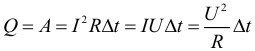
The law of converting the work of current into heat was experimentally established independently of each other by J. Joule and E. Lenz and is called Joule–Lenz law. Electric current power equal to the ratio of current work A to the time interval Δ t, for which this work was done, so it can be calculated using the following formulas:

The work of electric current in SI, as usual, is expressed in joules (J), power - in watts (W).
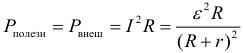
Closed circuit energy balance
Let us now consider a complete direct current circuit consisting of a source with an electromotive force ε and internal resistance r and an external homogeneous area with resistance R. In this case, the useful power or power released in the external circuit:
The maximum possible useful power of the source is achieved if R = r and is equal to:
If, when connected to the same current source with different resistances R 1 and R 2 equal powers are allocated to them, then the internal resistance of this current source can be found by the formula:
Power loss or power inside the current source:

Total power developed by the current source:
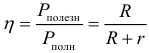
Current source efficiency:
Electrolysis
Electrolytes It is customary to call conducting media in which the flow of electric current is accompanied by the transfer of matter. The carriers of free charges in electrolytes are positively and negatively charged ions. Electrolytes include many compounds of metals with metalloids in the molten state, as well as some solids. However, the main representatives of electrolytes widely used in technology are aqueous solutions inorganic acids, salts and bases.
The passage of electric current through the electrolyte is accompanied by the release of a substance on the electrodes. This phenomenon is called electrolysis.
Electric current in electrolytes represents the movement of ions of both signs in opposite directions. Positive ions move towards the negative electrode ( cathode), negative ions – to the positive electrode ( anode). Ions of both signs appear in aqueous solutions of salts, acids and alkalis as a result of the splitting of some neutral molecules. This phenomenon is called electrolytic dissociation.
Law of Electrolysis was experimentally established by the English physicist M. Faraday in 1833. Faraday's law determines the amount of primary products released on the electrodes during electrolysis. So, the mass m substance released on the electrode is directly proportional to the charge Q passed through the electrolyte:
![]()
Size k called electrochemical equivalent. It can be calculated using the formula:
Where: n– valency of the substance, N A – Avogadro’s constant, M– molar mass of the substance, e– elementary charge. Sometimes the following notation for Faraday's constant is also introduced:
Electric current in gases and vacuum
Electric current in gases
Under normal conditions, gases do not conduct electricity. This is explained by the electrical neutrality of gas molecules and, therefore, the absence of electric charge carriers. In order for a gas to become a conductor, one or more electrons must be removed from the molecules. Then free charge carriers will appear - electrons and positive ions. This process is called ionization of gases.
Gas molecules can be ionized by external influence - ionizer. Ionizers can be: a stream of light, x-rays, electron flow or α -particles Gas molecules also become ionized at high temperatures. Ionization leads to the appearance of free charge carriers in gases - electrons, positive ions, negative ions (an electron combined with a neutral molecule).
If you create an electric field in the space occupied by an ionized gas, then the electric charge carriers will come into ordered motion - this is how an electric current arises in gases. If the ionizer stops working, the gas becomes neutral again, as it recombination– formation of neutral atoms by ions and electrons.
Electric current in a vacuum
Vacuum is the degree of rarefaction of a gas at which we can neglect the collision between its molecules and assume that the mean free path exceeds the linear dimensions of the vessel in which the gas is located.
Electric current in a vacuum is the conductivity of the interelectrode gap in a vacuum state. There are so few gas molecules that their ionization processes cannot provide the number of electrons and ions that are necessary for ionization. The conductivity of the interelectrode gap in a vacuum can be ensured only with the help of charged particles arising due to emission phenomena on the electrodes.
- Back
- Forward
How to successfully prepare for the CT in physics and mathematics?
In order to successfully prepare for the CT in physics and mathematics, among other things, it is necessary to fulfill three most important conditions:
- Study all topics and complete all tests and assignments given in the educational materials on this site. To do this, you need nothing at all, namely: devote three to four hours every day to preparing for the CT in physics and mathematics, studying theory and solving problems. The fact is that CT is an exam where it is not enough just to know physics or mathematics, you also need to be able to solve it quickly and without failures large number tasks for different topics and of varying complexity. The latter can only be learned by solving thousands of problems.
- Learn all the formulas and laws in physics, and formulas and methods in mathematics. In fact, this is also very simple to do; there are only about 200 necessary formulas in physics, and even a little less in mathematics. In each of these subjects there are about a dozen standard methods for solving problems of a basic level of complexity, which can also be learned, and thus, completely automatically and without difficulty solving most of the CT at the right time. After this, you will only have to think about the most difficult tasks.
- Attend all three stages of rehearsal testing in physics and mathematics. Each RT can be visited twice to decide on both options. Again, on the CT, in addition to the ability to quickly and efficiently solve problems, and knowledge of formulas and methods, you must also be able to properly plan time, distribute forces, and most importantly, correctly fill out the answer form, without confusing the numbers of answers and problems, or your own last name. Also, during RT, it is important to get used to the style of asking questions in problems, which may seem very unusual to an unprepared person at the DT.
Successful, diligent and responsible implementation of these three points will allow you to show an excellent result at the CT, the maximum of what you are capable of.
Found a mistake?
If you think you have found an error in educational materials, then please write about it by email. You can also report a bug to social network(). In the letter, indicate the subject (physics or mathematics), the name or number of the topic or test, the number of the problem, or the place in the text (page) where, in your opinion, there is an error. Also describe what the suspected error is. Your letter will not go unnoticed, the error will either be corrected, or you will be explained why it is not an error.